Session One
☰ MenuThe aims for this session are:
- Make all the connections between the motors and the Arduino UNO
- Move the robot forwards and backwards
First step: Hardware installation
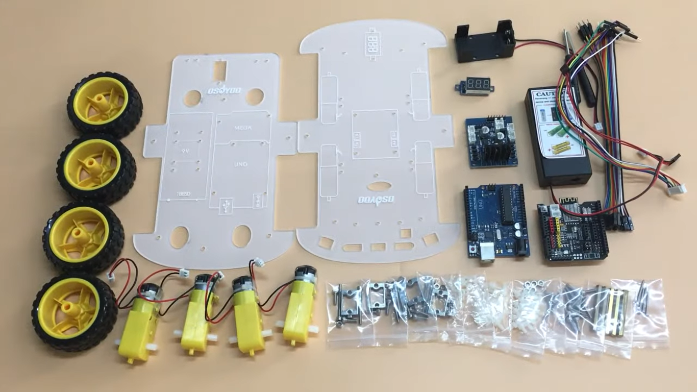
First of all, it is fundamental to prepare all the hardware required to permit the robot to work. The steps to follow to have all prepared are:
- Step 1. Remove the protective film on upper and lower car chassis
- Step 2. Fix motors with metal motor holders (check motor directions first!)
- Step 3. Intall Osoyoo Model X motor driver module in the correct direction
- Step 4. Install voltage meter in the lower chassis (to make sure the batteries are working)
- Step 5. Install Arduino UNO in the upper chassis
- Step 6 Install battery case in the upper chassis (minim voltage: 7.2V)
- Step 7. Connect 2 connectors of the battery to the Arduino UNO
- Step 8. Connect the 4 motors to Osoyoo Model X
- Step 9. Connect voltage meter to Osoyoo Model X with 3 female to female jumper wires
- Step 10. Connect upper chase with the lower
- Step 11. Connect upper chassis to lower chassis with five copper pillars and fix copper pillars with 10pcs M3*10 hex screws
- Step 12. Install 4 wheels onto the motors


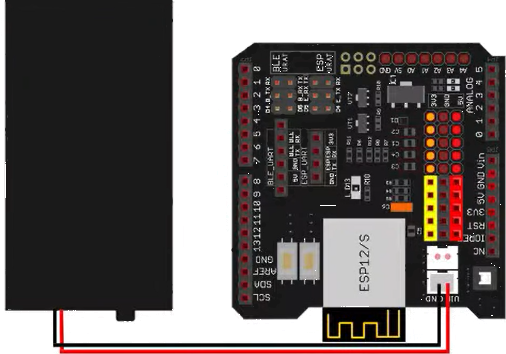

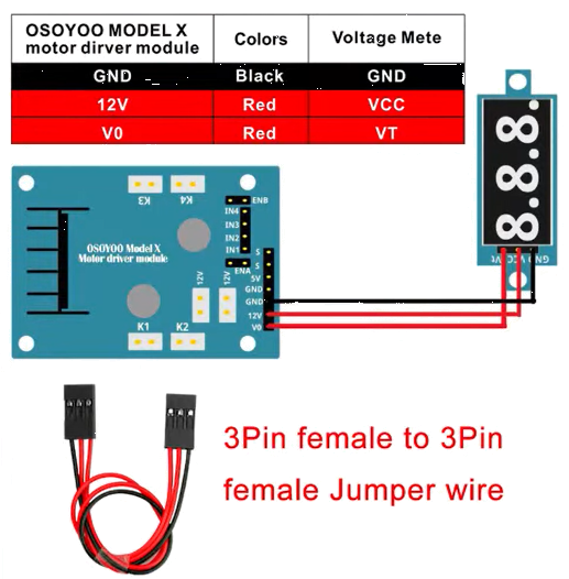
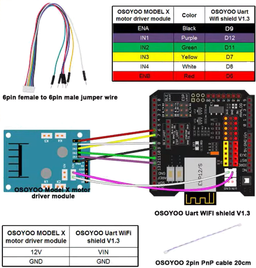


After following these steps, the main purposes of the Hardware section of this session have been acomplished as the installation is almost down.
Second step: Software installation
To create the code and send it to the Arduino, it is essential to install Arduino Software (IDE) (the version must be up to the 1.1.16).
The code used is the following:
#define speedPinR 9    //  RIGHT PWM pin connect MODEL-X ENA
#define RightMotorDirPin1  12    //Right Motor direction pin 1 to MODEL-X IN1
#define RightMotorDirPin2  7    //Right Motor direction pin 2 to MODEL-X IN2
#define speedPinL 6   // Left PWM pin connect MODEL-X ENB
#define LeftMotorDirPin1   11   //Left Motor direction pin 1 to MODEL-X IN3
#define LeftMotorDirPin2  9   //Left Motor direction pin 2 to MODEL-X IN4


/*motor control*/
void go_Advance(void) { //Forward
  digitalWrite(RightMotorDirPin1, HIGH);
  digitalWrite(RightMotorDirPin2,LOW);
  digitalWrite(LeftMotorDirPin1,HIGH);
  digitalWrite(LeftMotorDirPin2,LOW);
  analogWrite(speedPinL,200);
  analogWrite(speedPinR,200);
}

void go_Left(int t=0) { //Turn left
  digitalWrite(RightMotorDirPin1, HIGH);
  digitalWrite(RightMotorDirPin2,LOW);
  digitalWrite(LeftMotorDirPin1,LOW);
  digitalWrite(LeftMotorDirPin2,HIGH);
  analogWrite(speedPinL,200);
  analogWrite(speedPinR,200);
  delay(t);
}

void go_Right(int t=0) { //Turn right
  digitalWrite(RightMotorDirPin1, LOW);
  digitalWrite(RightMotorDirPin2,HIGH);
  digitalWrite(LeftMotorDirPin1,HIGH);
  digitalWrite(LeftMotorDirPin2,LOW);
  analogWrite(speedPinL,200);
  analogWrite(speedPinR,200);
  delay(t);
}

void go_Back(int t=0) { //Reverse
  digitalWrite(RightMotorDirPin1, LOW);
  digitalWrite(RightMotorDirPin2,HIGH);
  digitalWrite(LeftMotorDirPin1,LOW);
  digitalWrite(LeftMotorDirPin2,HIGH);
  analogWrite(speedPinL,200);
  analogWrite(speedPinR,200);
  delay(t);
}

void stop_Stop() {   //Stop
  digitalWrite(RightMotorDirPin1, LOW);
  digitalWrite(RightMotorDirPin2,LOW);
  digitalWrite(LeftMotorDirPin1,LOW);
  digitalWrite(LeftMotorDirPin2,LOW);
}

/*set motor speed */
void set_Motorspeed(int speed_L,int speed_R) {
  analogWrite(speedPinL,speed_L);
  analogWrite(speedPinR,speed_R);
}

//Pins initialize
void init_GPIO() {
	pinMode(RightMotorDirPin1, OUTPUT);
	pinMode(RightMotorDirPin2, OUTPUT);
	pinMode(speedPinL, OUTPUT);

	pinMode(LeftMotorDirPin1, OUTPUT);
  pinMode(LeftMotorDirPin2, OUTPUT);
  pinMode(speedPinR, OUTPUT);
	stop_Stop();
}

void setup() {
	init_GPIO();
	go_Advance();//Forward
  delay(2000);

  go_Back();//Reverse
  delay(2000);

  go_Left();//Turn left
  delay(2000);

  go_Right();//Turn right
  delay(2000);

  stop_Stop();//Stop

}

void loop() {
  go_Advance;
  go_Back;
}
With this code, the robot moves forwards and then backwards (in the void loop can be put any other functions previously defined).
Third step: Results
This is the first try it has been done.
As it is seen, only the right wheels are working. To solve this problem, the code was cheked and it was concluded that the left motor pins were not the correct ones.
So, after changing them, it is done the second try.
EXTRA INFORMATION: H-bridge
An H-bridge is an electronic circuit that switches the polarity of a voltage applied to a load. One of its applications is to allow DC (direct current) motors to run forwards or backwards.
The name is derived from its common schematic diagram representation, with four switching elements configured as the branches of a letter "H" and the load connected as the cross-bar.
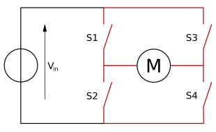
DC motor Driver
Changing the polarity of the power supply to DC motor is used to change the direction of rotation. This are the two basic states of an H-bridge:

Even though it is generally used to reverse the direction (or polarity) of the motor, it can also be used to 'brake' the motor (the motor comes to a sudden stop) or to let the motor 'free run' to a stop, as the motor is effectively disconnected from the circuit.
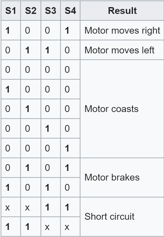
The following table summarizes operation, with S1-S4 corresponding to the diagram above. In the table below, "1" is used to represent "on" state of the switch, "0" to represent the "off" state.
